
A methodology was utilised to ensure that as far as was reasonably practicable, direct comparisons of all location devices could be made under comparable conditions and from a range of observation platforms. The methodology employed assumed no prior knowledge of the performance and limitations of any particular location device.
The components of prevailing weather were recorded throughout the field trials. These included; wind direction, wind speed, cloud cover, cloud type, precipitation, light intensity and visibility. Wind speeds and sea states were continuously recorded during the course of each trial by anemometer and by estimating the sea wave height. The location devices were tested under a wide range of sea states from calm to marginal. An attempt was made to trial all devices under a broad range of light intensities ranging from light to dark. Light intensity was monitored and recorded in lux (lumens per square meter) using a Gossen Lunasix F light meter.
3.2 LOCATION DEVICES
A variety of location devices available for use by divers on the surface were selected for field trials. A brief description of each device is detailed in Table 1. A summary of device specifications is detailed in appendix Table 21.
Table 1
Location devices used in trials
|
Location device |
Description |
|
Pyrotechnic rockets |
Pains-Wessex Miniflare 3 |
|
Pyrotechnic flare and smoke |
Pains-Wessex Day/Night Distress Signal |
|
Marker Dye |
High visibility green dye |
|
Surface Marker Buoys |
Polyform buoys and Delayed SMB's |
|
Folding Diver's Flag |
Day-glow Yellow, Red, Orange, Black and A-Flags |
|
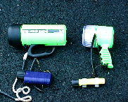
Torches |
MiniQ, SL4, UK400, UK1200 |
|
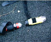
Strobes |
Seaman Sub Signal Flash and Jotrun |
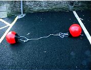
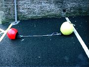
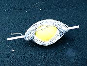
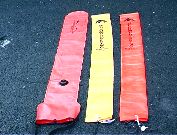
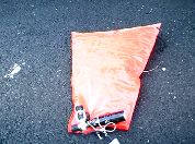
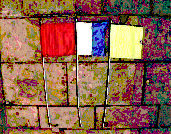
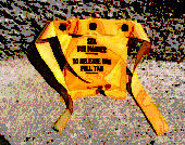
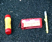
Polyform buoys vary in colour and size. Red, orange and pink are the most common although some divers use bright yellow. These were used in paired combinations and separated by a minimum of 2 m. These buoys had a diameter of approximately 40 cm. These devices are typical of those used by shellfish divers for position marking. Delayed SMB's included a red AP Valves self-inflating decompression marker buoy, red AP Valves decompression sausage (self sealing), and Bowstone red and yellow decompression sausages (open ended). The torches that were selected represented a range of power outputs and are typical of those used by divers as main and backup torches. Two types of marker dye were tested. Sea-Streak from Advanced Diving Products is a small tablet of solid dye that slowly dissolves when a white tear seal is pealed from the plastic pouch and exposed to water. Sea Marker Dye (from Presto Dyechem) retailed by BCD International is also a small plastic pouch which is pealed apart to release a cloth bag on a length of tape containing powdered dye. Both types of dye release a plume of bright green dye on contact with water. The folding diver's flags are assembled from three sections of hollow white plastic pipes that slot into couplings to form a pole 1.8 m in length. When folded, the pole sections are held together by a length of bungee cord running through the centre of each section. A square coloured pennant is attached to one end.
Location aids trialed.
 |
 |
 |
|
Polyform buoys
|
Self-deploying SMB
|
|
 |
 |
 |
|
Decompression sausages
AP Valves and Bowstone |
AP Valves self-inflating bag
|
Folding flags
|
 |
 |
 |
|
Strobes
SOS and Jotrun |
Torches
UK1200 UK400 SL4 MiniQ |
Sea Marker Dye
|
 |
||
|
Pyrotechnics
Day/Night Mk4 Miniflare 3 |
||
The observer eye height in the inflatable was just less than 2 m. Observation heights from the hard boat were between 3 m and 4 m and were made from the wheelhouse and bows. The skipper of each vessel and several University staff all undertook observations for location devices. A limited number of trials were also conducted in Shetland using the Sumburgh based Bristows SAR Coastguard helicopter for aerial observations from typical search altitudes. In the latter stages of the trials a relocation exercise for diver location devices was undertaken in Scapa Flow incorporating the search capabilities of two Lifeboats and the SAR helicopter.
The majority of trials were conducted in Scapa Flow, Orkney and a limited number of relocations by helicopter were undertaken in Shetland. The maximum relocation range of each device, observed from inflatable and hard boat was determined under a wide range of prevailing conditions. The trial area was a relatively sheltered body of inshore water that is not subjected to significant swell waves. Although an inshore area, Scapa Flow is subject to a substantial fetch from the South East through to the West. Consequently, this region can experiences sea waves of heights exceeding 1.5 m. Small swell waves are sometimes generated in this area at very high wind speeds.
Location devices were deployed in fixed positions by securing to a weighted shot line. As a standard against which all location devices may be compared, a series of location trials to simulate a diver on the surface with no additional location device was undertaken. A buoy was covered with a black neoprene diving hood and weighted below to represent a diver's head above water. The weight served to damp movement of the buoy. A relocation of a real, fully equipped diver was also undertaken for comparison. The folding flags required the attachment of small buoys to emulate the deployment height as a diver would hold the flag. Strobes were attached in an elevated position by fixing to the top of a diver's folding flag. Pyrotechnics and torches were activated from inflatable by holding them 0.5 m above sea level.
All deployment and relocation positions were recorded as a Global Position System (GPS) fix.
3.6.1 Method ADuring the initial trials, a wide range of devices were relocated by placing a selection of devices along a transect secured by weighted shot lines at each end. In the first instance, the initial approaches were made heading directly towards the mid-point of the transect to ascertain maximum relocation distances. When a visual sighting was made the search vessel recorded the GPS position fix. The search vessel then continued its search for the remaining, unsighted devices. The search vessels then made approaches from a variety of aspects to determine any differences in relocation distances.
3.6.2 Method BOn several trialing days, devices were deployed in random positions and attached to shot lines to prevent drifting. To simulate more realistic relocation potentials, observers did not witness the deployment of the devices. The search vessels then made approaches on headings chosen to cause the observers to search for the devices through a 120o sector.
3.6.3 Method CDevices were deployed in groups of three or four in extensive triangular or rectangular formations. The search vessels made approaches to all devices from a selection of headings to take prevailing wind directions into account. The formation of the devices allowed repetitive runs to be made between all devices, thus maximising the number and variety of relocation approaches. The devices were deployed in relatively open bodies of water, generally devoid of obvious landmarks.
3.6.4 Method DTwo days of trials were also conducted using a single deployment position for a selection of devices in turn. Each device was relocated from similar aspects. Headings were selected in order for the search vessel to run into, against and across the prevailing wind and wave direction. This method of relocation was used to standardise the relocation aspects in respect to the prevailing wind and wave direction.
3.6.5 Aerial locationDevices were deployed for aerial relocation on two occasions. Deployment method A was utilised in the first instance and subsequently, method B.
3.6.6 Search ExerciseA search exercise for diver location devices was undertaken on 20th March in Scapa Flow incorporating the search capabilities of the RNLI Stromness and Longhope lifeboats and Bristows SAR Shetland Coastguard helicopter. This exercise was co-ordinated by MRSC Pentland. A selection of location devices were deployed in predetermined locations within a search area of 8 square nautical miles (nm2) in an open expanse of Scapa Flow to assess the search capabilities of lifeboats and helicopter for these devices. Each lifeboat independently searched a sector of 4 nm2 employing a creeping line ahead with a track spacing of 0.2 nm (370 m) whilst the helicopter independently searched the total area at an altitude of 300 feet (90 m) utilising the same search pattern.
3.6.7 Location Distance CalculationsThe relocation distances were calculated between the deployment and relocation GPS position fixes using the following mathematics:
Departure = diference in longitude x cosMean latitude
Course = arctan (departure / diference in latutude)
Distance = (diference in latitude / cosCourse)
3.7 LOCATION DEVICE QUESTIONNAIRES
A questionnaire regarding location devices was distributed to over 80 recreational sub-aqua diving clubs in the UK (see appendix). The questionnaire was used to assess the current range of location devices presently used by this group of divers and their preferences for particular devices. Several shellfish divers based in Orkney were interviewed to evaluate their comments regarding the relocation of divers undertaking this type of commercial diving operation and to assess the range of location devices presently used by this group.